devices.esphome.io
Strong Helo PLUSB 2x USB Power Monitoring Plug (HELO-PLUSB-EU)
Strong Helo PLUSB 2x USB Power Monitoring Plug (HELO-PLUSB-EU)
Device Type: relayElectrical Standard: euBoard: esp8266Difficulty: Soldering required, 4/5

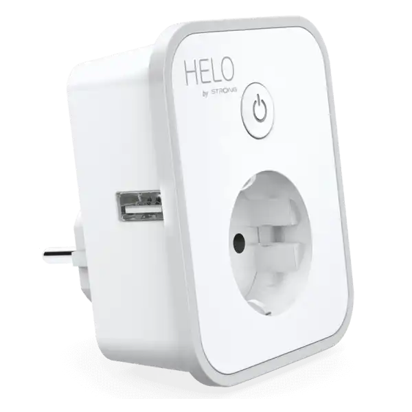
This plug has a socket output switched by a relay and a separately switchable dual USB power output. Has a rubber edge around the front face, and a push button above the socket. A red LED under the button switches on with the relay, and a blue one can be freely configured. It contains a TYWE3S module and a BL0937 power monitoring chip.
GPIO Pinout
| Pin | Function |
|---|---|
| GPIO00 | Button |
| GPIO04 | BL0937 CF |
| GPIO05 | HLWBL CF1 |
| GPIO12 | HLWBL SELi |
| GPIO13 | Status LED (inverted) |
| GPIO14 | Relay 1 (socket) |
| GPIO15 | Relay 2 (USB power) |
Initial Setup
Remove the 4 screws at the back of the device. Requires triangular bit to unscrew case, but Torx 7 also works. Remove the daughterboard by unscrewing the interal screws. The daughter-board is held by 3 internal smaller screws, remove that too, but be careful as wires are short. No need to remove the main board, as the MCU is on the daughter-board. Disconnect the internal cable connecting the two. This way the module becomes relatively easily accessible.
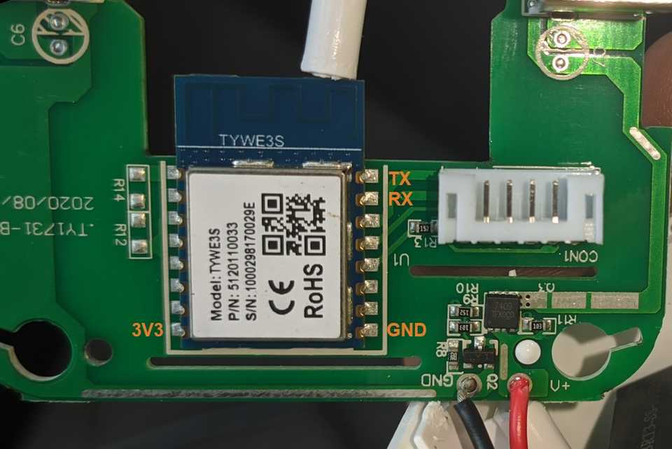
The TYWE3S module is ESP8266-based, so it can be flashed directly with ESPHome. You need to solder your USB-TTL adapter to the RX, TX, GND and 3V3 pins, then just hold down the onboard button while powering on the adapter. When only the red LED lights up, the board is in bootloader mode.

Basic Configuration
substitutions: device_name: plug-helo-plusb friendly_name: "Helo PLUSB Plug" device_description: "Strong Helo PLUSB 2x USB Power Monitoring Plug (HELO-PLUSB-EU)" voltage_div: "1655.66630552546" # Lower value gives lower voltage readout. Calibrate for higher accuracy. current_res: "0.00092" # Higher value gives lower watt readout. Calibrate for higher accuracy. current_mul: "0.914285714285714" # Muliplier for current sensor filter. Calibrate for higher accuracy.
esphome: name: ${device_name} comment: ${device_description}
esp8266: board: esp01_1m restore_from_flash: true
sensor: - platform: hlw8012 model: BL0937 sel_pin: number: GPIO12 inverted: true cf_pin: GPIO4 cf1_pin: GPIO5 change_mode_every: 4 update_interval: 10s current: name: ${friendly_name} Current disabled_by_default: true filters: - multiply: ${current_mul} voltage: name: ${friendly_name} Voltage power: name: ${friendly_name} Power current_resistor: ${current_res} voltage_divider: ${voltage_div}
binary_sensor: - platform: gpio pin: GPIO00 id: button internal: true filters: - invert: - delayed_off: 10ms on_multi_click: - timing: #short press to toggle socket relay - ON for at most 1s then: - switch.toggle: id: switch_skt - timing: #long press to toggle USB power output - ON for at least 1s then: - switch.toggle: id: switch_usb
output: - platform: gpio pin: GPIO14 id: relay1 - platform: gpio pin: GPIO15 id: relay2
switch: - platform: output name: ${friendly_name} Socket icon: mdi:power-socket-de restore_mode: RESTORE_DEFAULT_OFF output: relay1 id: switch_skt - platform: output name: ${friendly_name} USB icon: mdi:usb-port restore_mode: RESTORE_DEFAULT_OFF output: relay2 id: switch_usb on_turn_on: light.turn_on: onboard_led on_turn_off: light.turn_off: onboard_led
light: - platform: status_led id: onboard_led internal: true pin: number: GPIO13 inverted: true